Sunday, August 29, 2010

PATHFINDER Contd....PART 2


Input system:

Line sensor module:


LED PHOTRANSISTOR pair

Each sensor module consists of one emitter (LED) and one receiver (Photo transistor).
If white surface is present beneath the LED, rays are reflected and are sensed by the receiver phototransistor’s base, the phototransistor gets on.
While in case of black surface, the light gets absorbed and hence receiver phototransistor become off.
Thus the presence of white and black surface is sensed by the sensor module and the system can follow a line.

IR obstacle sensor module::

IR LED for emitter IR photodiode for receiver

The obstacle sensor consists of one emitter (IR LED) and one receiver (IR Photo diode).
If obstacle is present the IR rays are reflected back and are sensed by the receiver photo diode, the photo diode gets forward biased (on).
While in case of no obstacle, the IR rays don’t get reflected back and hence receiver photo diode become reverse biased (off).
Thus the presence of obstacle is sensed by the sensor module.


CONTD.........

Tuesday, August 10, 2010

PATHFINDER...PART-1

PATHFINDER

PATHFINDER


Aim: - A fully autonomous line tracking and sensing robot.

Objective:

A fully autonomous robot capable to sense obstacle from the middle of any grid and take automatic decision of what turn is to be taken. And when no obstacle is sensed it will follow line and will stop at the mid point of the next grid. Thus it can travel through the grids avoiding obstacles (closed door of grid) and ultimately stops at the last grid where no door kept open.


Abstract:
The robot ‘Path Finder’ is a self operating robot that detects any obstacle being present in front of it and turns 90 degree and follows a line that is drawn on the floor. The path consists of a black line on a white surface (or vice versa).The control system used must sense a line and maneuver the robot to stay on course, while constantly correcting the wrong moves using feedback mechanism, thus forming a simple yet effective closed loop System. The robot is designed to follow only obtuse angles where 90 maximum 90 degree turn is required. Now the control system as well senses any obstacle and taking 90 degree turn.

Arena has 9 grids with total 12 doors. The floor is black containing white strip at centre. Some doors will be closed and there will be only one path open the robot has to move along the path.


Basic design and requirements:

The robot is built using ATmega16L (micro controller IC), L293D (comparator IC), LED, photo transistor [L14G3] (line sensor module), IR emitter receiver module (obstacle sensor).
The base of the robot is made wooden and two stepper motor controls its locomotion with a supporting caster wheel in front.
When the obstacle sensor detects any obstacle it automatically 90 degree turn and goes to next cell following a line given on the floor.
Thus it can travel a (N*N) grid matrix without colliding with closed door and following a straight line to remain in the center position of grid always.


Basic operation:

The basic operation of the robot can be broadly classified under 3 categories:
1. obstacle sensing
2. line sensing
3. locomotion controlling


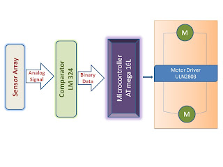
Block diagram
:

  • First sensor array senses the ambient like obstacle sensing and line sensing, as a continuous analog voltage form.
  • Next this analog signal is fed to comparator unit and made digital on off pulse depending upon the threshold limit.
  • This digital input is fed as input of micro controller unit and it processes the input.
  • Micro controller unit produces output that controls the locomotion of the robot: micro controller output is fed at motor driver unit that gives sufficient current to drive the motor.


REST PART WILL BE PUBLISHED SOON.................